


If you had X-ray vision and could peer into the ground beneath your feet, what would you see? A geophysical technique called Ground Penetrating Radar (GPR) helps us do just that—but using radio waves instead of X-rays. With uses ranging from mapping tree roots to locating gravesites, GPR harnesses the electromagnetic properties of materials to give us a fast, valuable way to learn about the Earth’s subsurface.
How does GPR work?
Like other radar (Radio Detection and Ranging) systems, GPR uses radio waves to detect and determine the location of something we’re interested in. For GPR, this “something” is buried underground, and could be a physical object (like a pipe or other utility), a natural layer (like bedrock or a soil horizon) or even the absence of material (like a burrow or grave shaft). GPR uses radio waves to “scan” and image Earth’s subsurface without having to physically dig or disturb the ground.
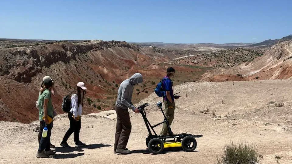
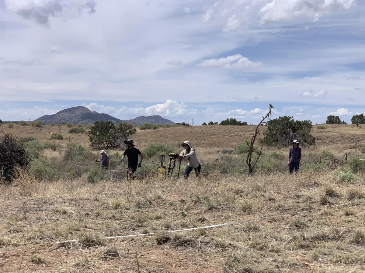
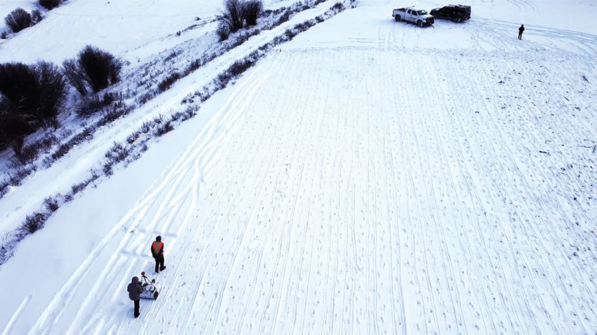
Modern GPR systems contain three main components: a control unit, an antenna that sends out radio waves (the transmitter), and an antenna that receives radio waves (the receiver). Most commonly, the transmitter and receiver antennas are part of the same system, hitching a ride together on a pushcart that looks a bit like a high-tech lawnmower.
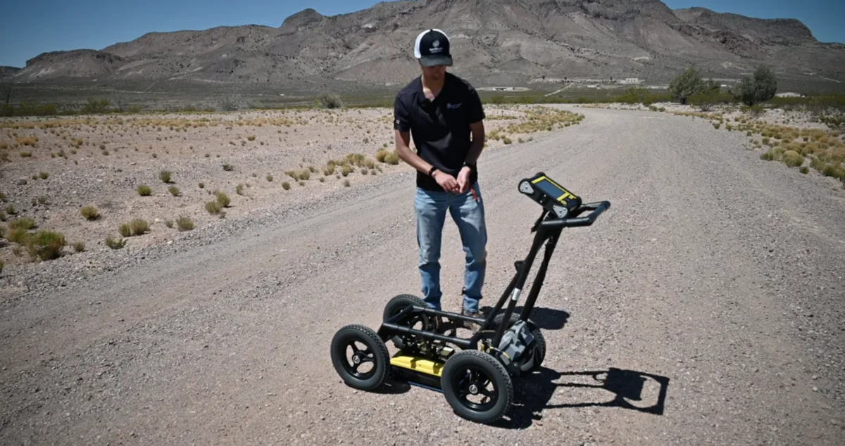
To collect data, the GPR operator begins pushing the GPR in a straight line—or transect—on the ground. As the GPR system is moved, the transmitter antenna sends out pulses of radio waves, each lasting no more than a few nanoseconds.
As a radio wave speeds down into the Earth below, it encounters different materials, each with different electromagnetic properties. For GPR, the most important of these properties is the dielectric permittivity, or the amount that the positive and negative charges in a material separate when they get exposed to an electrical field.
If, on its journey downwards, the wave suddenly encounters a material with very different permittivity, it can actually be reflected back up off this “anomaly” towards the ground’s surface. Not all of the energy returns—some gets scattered off the material, free to reflect off another buried object or eventually dissipate. Picture the transmitter and receiver trying to play catch with a handful of bouncy balls: the transmitter “throws” them down, where they hit a buried object; some get deflected off the object and speed away, but a few bounce back up to get snatched up by the receiver.
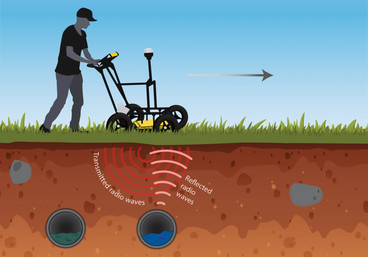
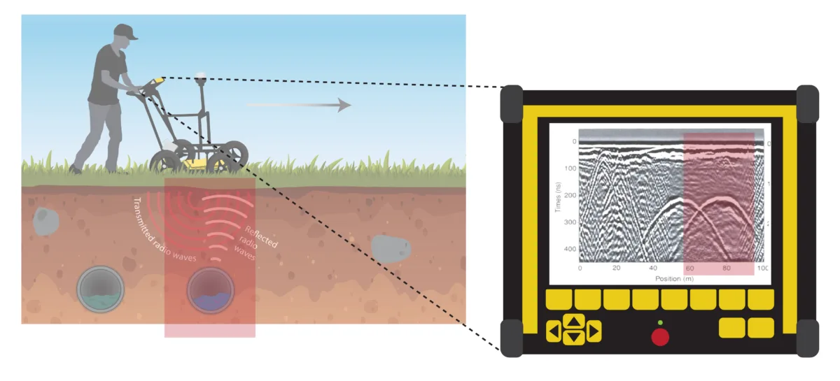
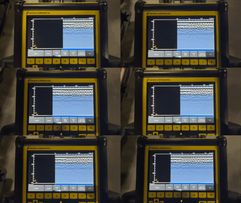
Having caught this bouncy wave, the receiver antenna then measures its strength and the time it took to return. Based on these values, the control unit can calculate the depth of the subterranean anomaly. This information then gets displayed visually in the form of a radargram, which depicts a cross-section slice of the ground below. Buried layers show up, unsurprisingly, as horizontal bands in the radargram. Buried objects are a bit stranger: they appear as hyperbolas (“frowning” curves), with the apex point of the hyperbola corresponding to the object’s center.
If you’d like to try it out yourself, you can check out this widget to make your own radargram diffraction patterns.
The wide world of GPR
In both commercial and research spheres, GPR has become a foundational technique for anyone who wants to see below-ground—with wide-ranging applications from locating underground utilities to measuring the thickness of glaciers to even detecting unexploded landmines.
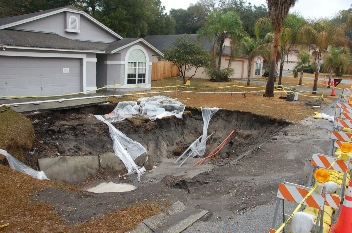
For Florida residents, GPR is used to detect a hidden and destructive threat: sinkholes. Florida sits on a slab of carbonate rocks—limestone and dolostone—that is easily dissolved by acidic groundwater. This dissolution creates karst terrain, a topography characterized by extensive channels under the ground and subsidence (in the form of sinkholes and depressions) on the surface. Floridians concerned about their land’s stability can hire private surveying companies, who use GPR to scan the ground for subsurface sinkholes and voids to detect the threat before collapse occurs.
In the world of archeology, GPR can be used to “excavate” a historical site without ever piercing the ground. In 2016, student researchers of the Summer of Applied Geophysics (SAGE) concluded a decade-long effort to map Pueblo San Marcos, an archeological site located near Santa Fe, New Mexico. During the field campaign, SAGE members surveyed the site with GPR and other geophysical techniques to collect data within “El Mapa Grande,” an area spanning thousands of meters. GPR’s ability to “see” beneath Earth’s surface revealed features like middens (ancient waste dumps), kivas (spaces used for religious ceremonies and other important events), and multi-room structures.
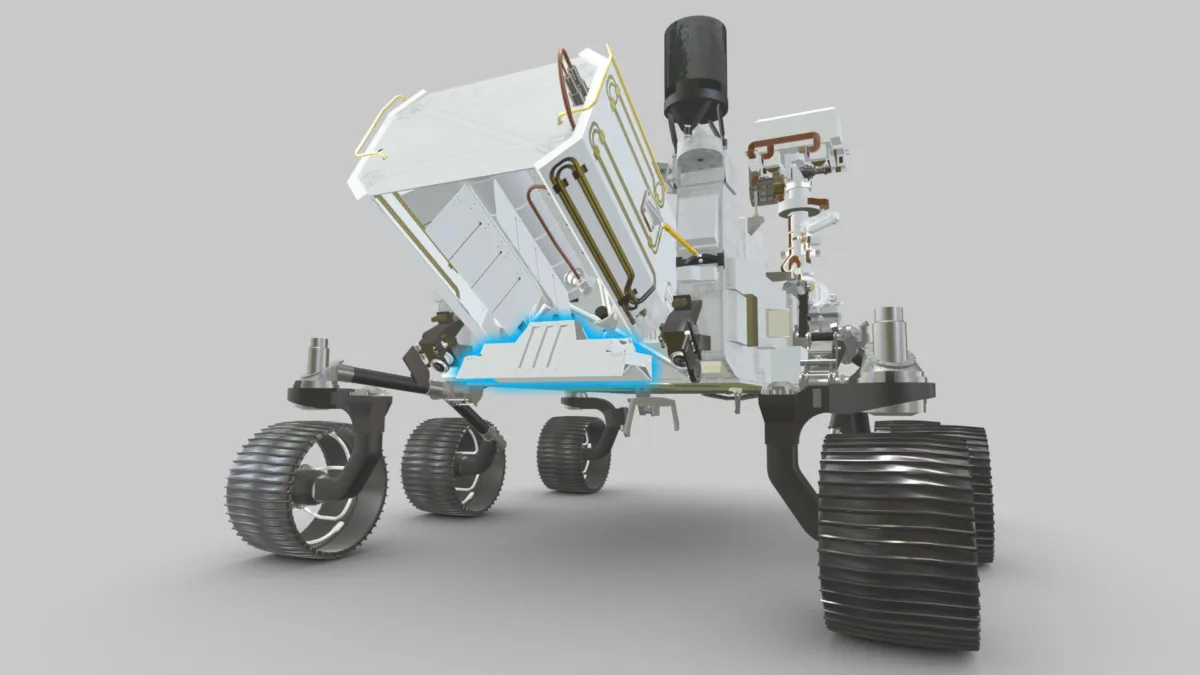
Scientists are also using GPR to investigate whether Mars could have hosted extraterrestrial life at some point in its history. In 2020, GPR hitched a ride to the Red Planet on Nasa’s Perseverance rover in the form of the Radar Imager for Mars Subsurface Experiment (RIMFAX).
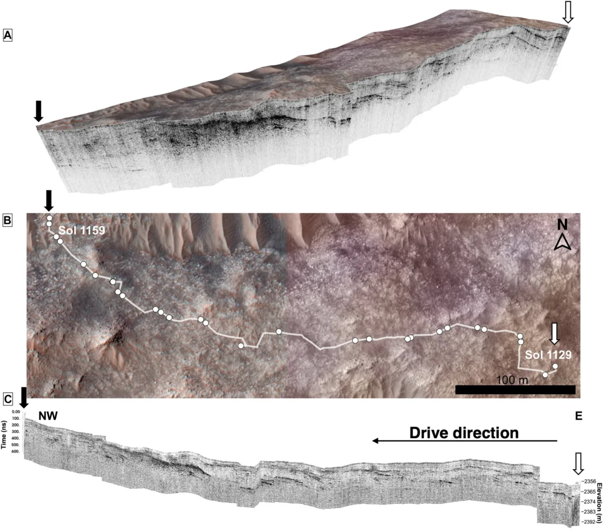
RIMFAX journeyed across Martian landscapes in 2023 and 2024, scanning the subsurface at depths of over 35 meters—around 1.75 times deeper than previously studied. The GPR radargrams revealed river and delta-related land structures hidden under Mars’s Jezero Crater. This buried evidence of running water in Jezero’s history suggests that the crater could have potentially been habitable for life earlier than previously believed.
In a much more sobering case, GPR is currently being used in investigations into the deaths of Native children at Canada’s eighteenth and nineteenth-century residential schools. In 2021, the Tk̓emlúps te Secwépemc Nation announced that they had used GPR to find evidence of 215 unmarked graves outside the Kamloops residential school in Western Canada. Since this highly publicized investigation, GPR has been used across Canada to identify hundreds of other unmarked burials, amounting to over 1,800 suspected or verified graves.
A deeper look: GPR’s strengths and weaknesses
The non-invasive nature of GPR means that a large amount of information can be learned about a subsurface area without the need to do any digging. This feature is especially useful for locating and documenting objects that could be damaged or destroyed if excavated. Depending on the choice of antenna, the resolution of GPR data can be very precise—as high as several centimeters.
In addition to being low-impact and high-resolution, GPR is quick: unlike techniques that require hours of data collection and processing to get any results, GPR is simple to operate and provides results in real time. As a GPR operator moves the device over a section of ground, the radargram of that area appears on the read-out screen.
Of course, GPR doesn’t come without its limitations. One large way it differs from the “X-ray vision” ideal is that GPR indicates where something is, but not what that thing is. Based on one transect, it can be difficult to tell if a located point anomaly is a pipe, a thick tree root, or a host of other buried objects.
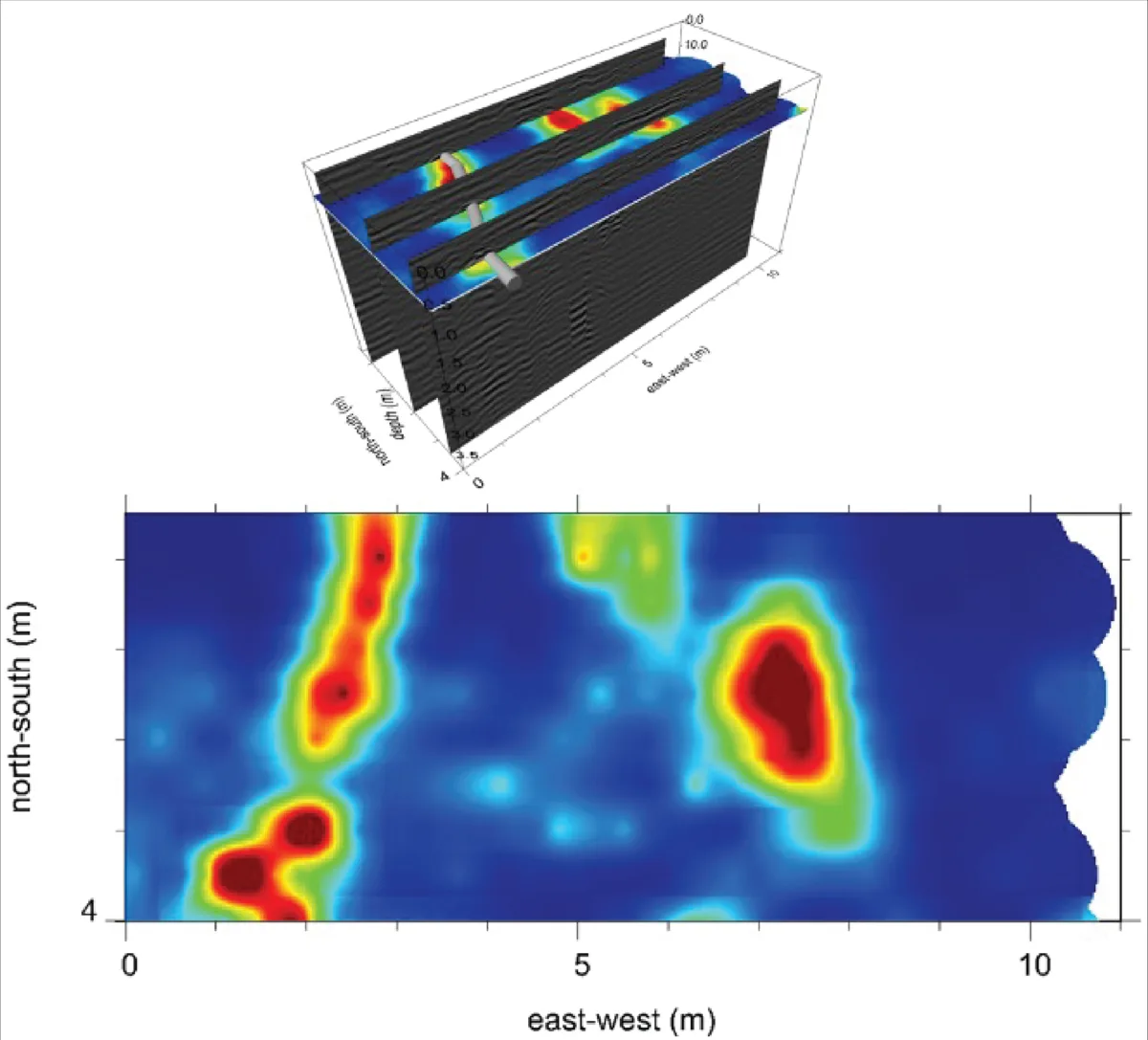
We can start to address this problem by taking multiple side-by-side GPR profiles of an area and combining their results into a depth slice. While radargrams represent a cross-section view of the ground below, depth slices show a birds-eye view of the data; this perspective shift helps to clarify the actual shape of subterranean features. Imagine slicing through a pipe and looking at it head-on: how could you know its length? You’d have to shift your view and look down at the pipe to actually get a sense of its shape.
Another factor that plays a large role in the effectiveness of GPR is its Depth of Investigation (DOI)—the distance that GPR is able to “see” down into the ground. This depth can be as shallow as centimeters to as deep as tens of meters. But what dictates the DOI? And why is this range so large?
Part of this equation is up to the operator. Like many things in life, GPR presents a tradeoff: using radio waves of lower frequencies allows us to see deeper but at lower resolution, while higher frequencies provide more clarity but a smaller range. When deciding what frequency to use, GPR operators need to decide whether they’d rather prioritize seeing clearly or seeing farther.
However, this choice is only part of the picture. The subsurface material (sandy soil, wet mud, concrete, etc.) plays a large role in determining the DOI for a certain GPR survey. Substances that conduct electricity tend to absorb the incoming radio waves, causing the signal to die out at very shallow depths. Because clay-rich soils and groundwater are conductive—and also widespread—it’s hard to find ideal natural conditions for GPR. To see for yourself how different ground materials impact the strength of the GPR signal, you can check out this widget.
The effectiveness of GPR is limited not only by characteristics of the subsurface but also by features on the surface itself. While it’s useful to visualize radar waves getting shot down from the transmitter into the ground, in reality these waves are spherical, released from the transmitter in all directions—including above the ground. As a result, objects on the Earth’s surface that have their own electromagnetic fields (like power lines and electrical towers) can interfere with the GPR radio signal and complicate interpretation of results.